-

-
400 South Salina St. Suite 201,
Syracuse, NY 13202
The Implications of Cryptocurrency on Data Center Cabling Designs
Free Whitepaper
DATA CENTER CABLING DESIGNS FOR CRYPTOCURRENCY
Over the past few years, there have been more and more reports in the news about cryptocurrency. In short, cryptocurrency is a digital asset meant to be used as a medium of financial exchange. It is essentially encrypted digital money and any transactions using cryptocurrency can take place independently of a central bank or financial institution.
One of the most noted examples of cryptocurrency is the product called Bitcoin, although it does have competitors like Ethereum, Ripple and Litecoin.
Some stories report how volatile digital currency transactions can be, while others say it’s the future of commerce on a global scale. The upside is it can eliminate the fluctuation of individual currency values and exchange rates; like the dollar being used to purchase a product in a country that uses the euro as money. The downside is that digital currency is simply information stored on a hard drive or flash drive. If the drive is somehow corrupted, or a virus invades the user’s computing equipment, that digital currency can be lost permanently.
This paper is not meant to weigh the merits of cryptocurrency, or even to address its pros and cons. But the rise of cryptocurrency has led to some new digital processes that require new computing needs. And when this happens, cabling and data center infrastructures are always affected. It is the intent of this paper to delve into the implications of these new computing processes.
The rise of cryptomining
Cryptocurrency has given rise to the new concept of cryptomining. Cryptomining is the process by which transactions are verified and added to the public ledger, known as the block chain, and also the means through which new cryptocurrency is released. The mining process involves compiling recent transactions into blocks and trying to solve a computationally difficult puzzle.[1]
Recently we have seen a sharp spike in new cryptocurrency data centers being built. Some are being built in existing infrastructures like an old manufacturing facility where power is available and square footage inexpensive.

The largest venue of growth that we are seeing is in locations that are more suited to a typical data center footprint. These sites have cooling capabilities along with dual power supplies. The space may or may not have a raised floor.
A typical cryptocurrency data center has cryptomining machines that perform the software function of managing transactions and completing the transaction itself. The cryptomining hardware comes in several different sizes ranging in hashpower (speed at which a compute is completing an operation), power efficiency, cryptocurrency earned per month, and cost.
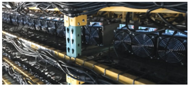
The cryptomining machines are rectangular in size and stacked on racks that look like warehouse or baker’s shelves. A typical application can have 64 to 96 miners on one 10-foot tall rack. The racks are taller and wider than a standard compute rack and not individually cooled. One rack will have one or two Ethernet uplink or leaf switches that connect back to a network core or spine switch.
Figure #1 – Miners on warehouse shelving with individual power cords and copper Ethernet connections to an uplink switch.
Designs for cryptomining
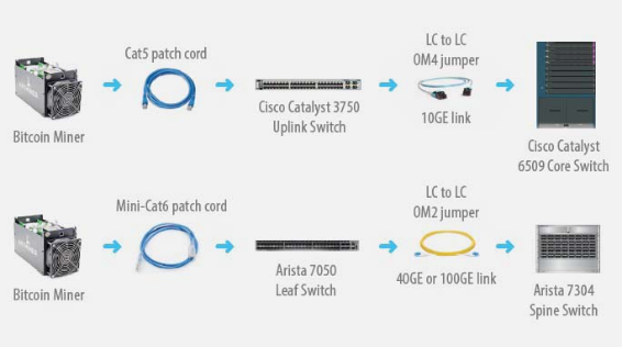
Higher-end applications could have an Arista 7050 leaf switch connecting back to an Arista 7304 spine switch. The connection from the miner to leaf would be a CAT6 patch cord. The connection from the leaf switch to spine switch would be with two single-mode jumpers running 40GE or 100GE. Since the data center is large, single-mode glass and optics are chosen to meet the distance requirements over 100 meters. This application most likely has two separate fabrics and spine switches.

When designing a structured cabling plant for higher-speed applications, having patch panels to replicate the spine switch ports helps manage growth at the spine switch. Also, having a break in the fiber link at the spine switch and the leaf switch allows the cabling plant to migrate to higher speeds in the future. This leaves the fiber trunks in-between the back of the patch panels to remain in place and operate effectively to support speed increases like 40GE to 400GE. All it would require is to replace the jumpers in the front of the patch panels to match the new higher-speed optic.
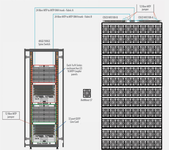
Figure #3 shows a design with port replication patch panels above two Cisco N9504 spine switches. A Cisco N9504 holds four 32-port QSFP line cards with 40GE SR-4 optics. Above each spine switch are four 1U patch panels with two slots. These two slots hold two 16-port MTP coupler panels numbered #1 to #16 and #17 to #32 to mirror each line card.
Figure #3 – Port replication patch panels above Cisco N9504 spine switches.
One 1U enclosure replicates one 32-port line card. As more miner racks are added to the data center with two leaf switches for each miner rack, they are connected back to the spine.
MTP jumpers plug into the N9504 line card 40GE SR-4 optics and into the front of the patch panel. On the back side of the patch panel are 24-fiber MTP to MTP OM4 trunks that run to another 6-port MTP coupler panel mounted between the two Cisco N93108 leaf switches on the top of the miner rack.
From the 6-port MTP coupler panels, two MTP jumpers plug into each of the two leaf switches. And finally the two N93108 leaf switches offer 48 ports each to the 96 miner machines in each rack. These connections are made with reduced diameter CAT6 patch cords that reduce cable diameter by 50% over standard CAT6 cable and are easier to manage on the miner rack.


